
RANDOM PAGE
SITE SEARCH
LOG
IN
SIGN UP
HELP
To gain access to revision questions, please sign up and log in.
A2
Stepper Motors
- Stepper motors rotate through precise angular steps giving perfect position control.
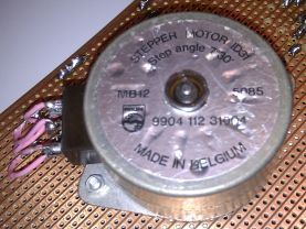
- Stepper motors are manufactured with steps per revolution of 12, 24, 48, 72, 144, 180, and 200.
- These give shaft rotation angles of 30, 15, 7.5, 5, 2.5, 2, and 1.8 degrees per step.
- Stepper motors come in bipolar and unipolar versions with both 4 pole or 6 pole devices.
 7.5o steps
3.75o steps
7.5o steps
3.75o steps
For more precise control, a stepper motor is needed. These are used when accurate position control is needed. Examples include robotic movement control, printer head movement control and disk drive head positioning.
- They step through a small known angle so it is possible to know the exact angular position of the motor.
- They are usually small.
- They are used for precise movement control in robotics and also in computer printers and disk drives.
- Ideal for controlling small precise movements in either direction.
- Hard and expensive to make very large stepper motors although kilowatt powers are available.
- More complex electronics is needed to control the motor, involving programming, data tables and a PIC chip or microcontroller.
- Accurate control is possible without negative feedback and a closed loop although this is sometimes included for additional safety and reliability.
- Difficult to control at high speeds.
- Poor efficiency converting electrical energy to mechanical.
- The rotation angle of the motor depends only on the input pulses.
- The motor has full torque at standstill if the electromagnets are turned on.
- Precise repeatable positioning is possible without positional drift.
- Excellent start/stop/reverse response.
- Reliable because there are no sliding contact brushes in the motor.
- Easy to build open-loop motor control systems.
- Excellent low speed performance especially with a gear box.
Unipolar Stepper Motor - Five or Six Connections
Connection 1 and 2 are sometimes joined together inside the motor.
Driver Circuit
- Unipolar motors have centre tapped coil windings.
- Only half the coil is energised at any time.
- If current flows from A to 1, the magnetic field will be established.
- If the current flows from B to 1, the field will be reversed.
- Likewise for coil 2.
- Four simple MOSFET switching circuits can be used to drive these coils.
- Bipolar transistors could be used instead.
Bipolar Stepper Motors - Four Connections
To reverse the magnetic field in the coils, an H-Bridge circuit is used. This is more complex than the unipolar arrangement above.
This circuit is able to energise the stepper motor coils in either direction. Two H-Bridge circuits are used, one for each coil.
Stepper Motor Drivers
- Four coil stepper motors can be controlled with four MOSFET switch circuits.
- Bipolar motors need the current to be reversed so H-Bridge controllers are ideal.
A Possible Physical Layout
Here is an approximation of one possible physical layout for a stepper motor. Only two of the eight coils are shown.
reviseOmatic V3
Contacts, ©, Cookies, Data Protection and Disclaimers
Hosted at linode.com, London